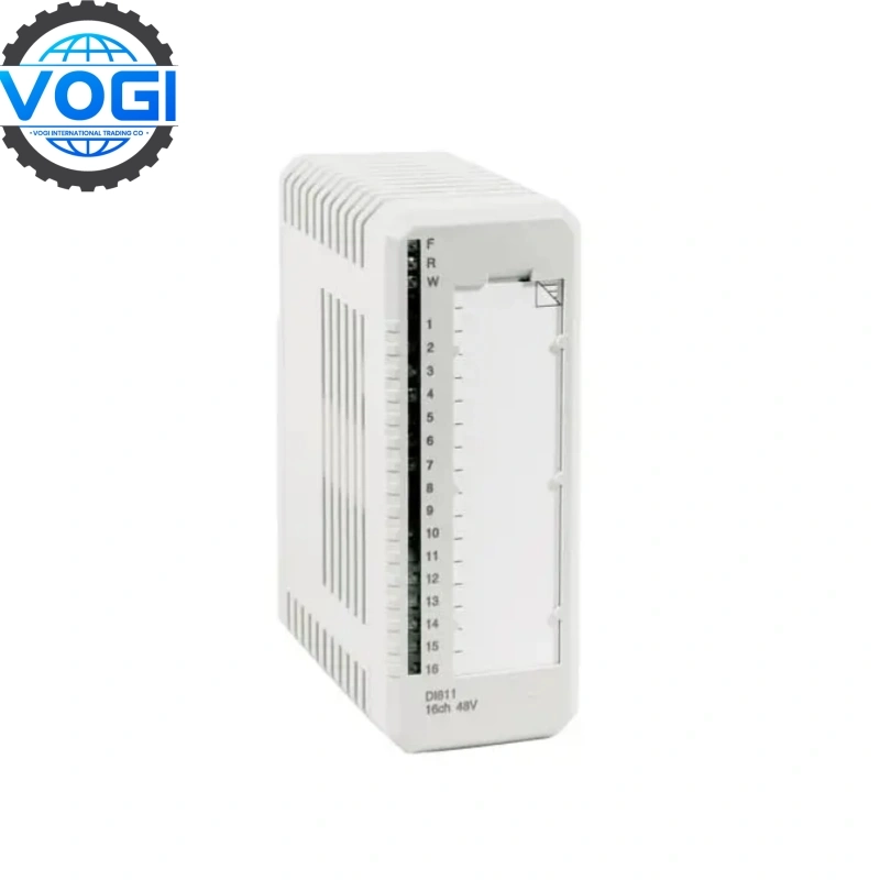
High-Precision Speed Signal Acquisition and Processing
- Wide-Range Signal Adaptation: Supports 0-20kHz pulse signal input (compatible with mainstream speed sensors such as Hall Effect sensors and photoelectric encoders), enabling full-scale speed monitoring from low-speed startup (e.g., motor startup speeds below 10 rpm) to high-speed operation (e.g., spindle speeds above 10,000 rpm).
- Multi-Dimensional Signal Conditioning: A built-in three-stage signal optimization circuit first suppresses electromagnetic interference from industrial sites through a differential filter circuit. A signal amplification module then calibrates weak pulses to the standard 0-5V range. Finally, a waveform shaping circuit converts irregular signals into standard square waves.
- High-precision digital conversion and data calculation: The sensor automatically calculates speed using the formula "Speed (r/min) = Pulse frequency (Hz) × 60 ÷ Number of pulses per sensor revolution," with a measurement accuracy of ±0.5% of full scale. A built-in temperature compensation algorithm corrects for counting deviations caused by ambient temperature changes (-25°C to +55°C) in real time, ensuring measurement stability across the entire temperature range.
Configuration Notes
- Ensure that the host computer and module parameters such as the ASDU address, TCP port, data bits/parity check mode are consistent. Also, set a reasonable TESTFR test frame period (usually 10-30 seconds) to avoid false positives.
- Ensure that the output signal type (pulse/analog) and signal amplitude of the connected speed sensor match the module input specifications. For example, the amplitude of the pulse signal must be within the 5-24V range supported by the module.


