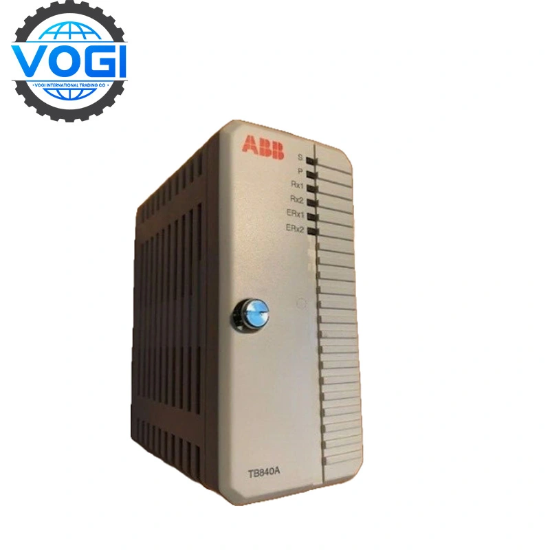
ABB PU515A 3BSE032401R1 Real-Time Accelerator
| Brand | ABB |
| Model Number | PU515A |
| Order Number | 3BSE032401R1 |
| Unit Price | $3000 |
| Country Of Origin | Sweden and Switzerland |
| Weight | 0.55KG |
| Certificate |
C/O from the Chamber of Commerce C/Q from the manufacturer |
| Warranty | 12 Months |
| Inventory Qty | 5 |
ABB PU515A 3BSE032401R1 is a Real-Time Accelerator, Its in an 800xA for Advant Master Connectivity Server can act as an Engineering Board.
ABB PU515A Key parameters
|
Parameter |
Specification |
|
Product ID |
REP3BSE032401R1 |
|
Catalog Description |
PU515A Real-Time Accelerator(RTA),PCI |
|
Product Type |
Communication_Module |
|
Customs Tariff Number |
8517620000 |
|
Categories |
Control & Communication → Advant Common – Communication Modules → PU515A MasterBus 300 Interfaces |
Account Number 88800006406771
Account name Vogi International Trading Co., Limited
(* If the account name exceeds the available space, please continue in the address field.)
SWITF/BIC Code WIHBHKHHXXX
Bank name OCBC Hong Kong Branch
Bank address 161 Queen's Road Central, Central, Hong Kong
Country/Region Hong Kong (China)
Account type Business Account
Bank code 035
Payment method For the payment of goods, please make a FPS/CHATS/SWIFT Payment
Notes Please include the following memo/message to receiver when making a payment: [Buyer Name] [Invoice/Contract Number] [Product]
How to install ABB PU515A
- Disconnect the computer power cord from the power line.
Remove the computer power cord from the power line before removing the cover.
There are unisolated and potentially fatal power line voltages present under the cover.
- Remove the computer cover. Refer to the computer hardware manual for details.
Wear a properly grounded antistatic wrist strap and handle the PU515A with care.
Static discharges may damage the PU515A when it is removed from the antistatic
bag. Do not touch connectors with bare hands.
- Unpack the PU515A.
- Detach the plastic handle from the PU515A, if required.
- Remove the cover plate of any PCI slot and mount the PU515A in the slot.
- Install the computer cover. Refer to the computer hardware manual for details.
- Connect the computer power cord into the power line.
- Turn on the computer.


